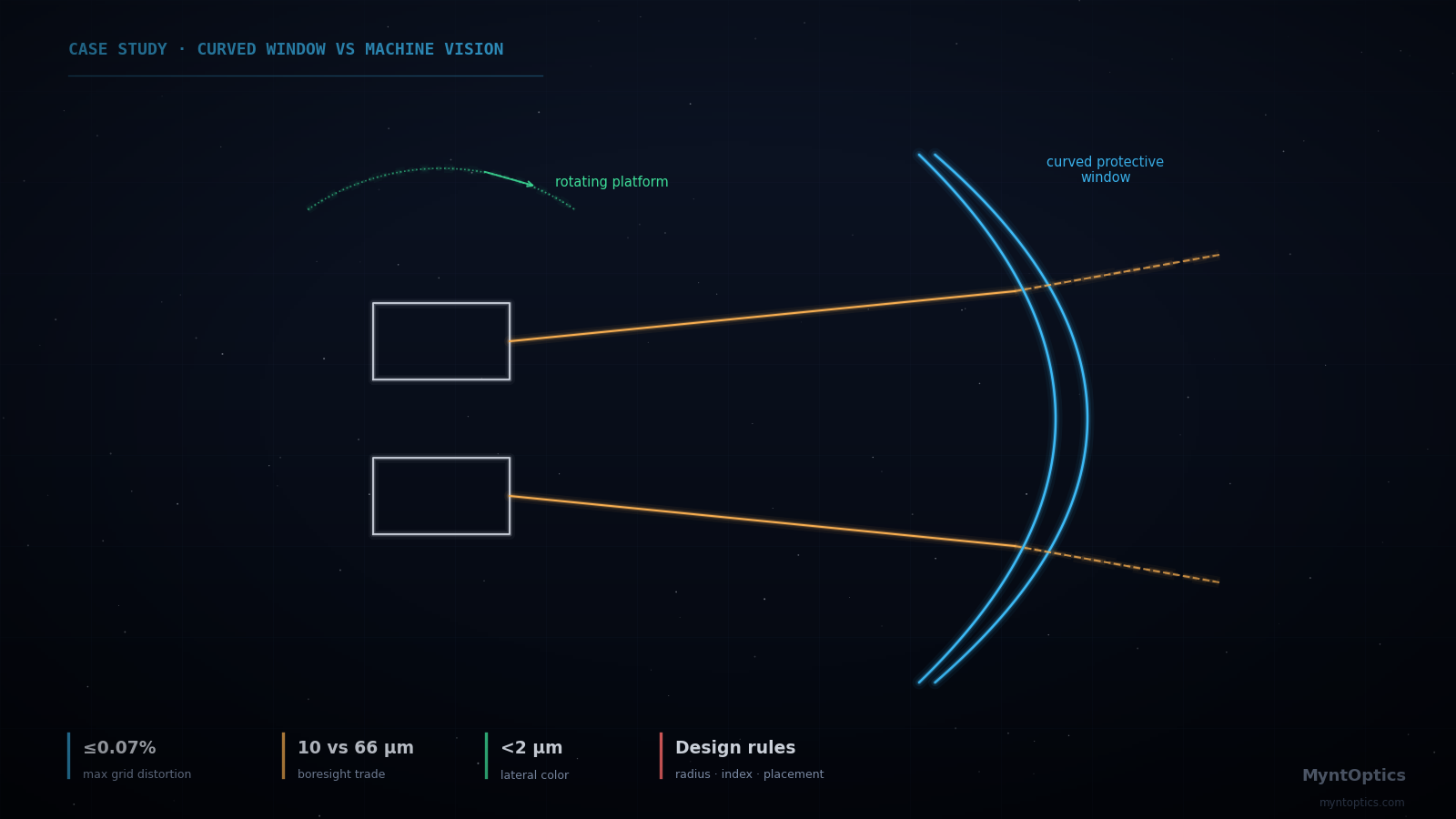
A camera rotating behind a curved window sees a different slice of glass at every gaze angle — and the boresight shift depends critically on where the lens pupil sits.
Application
Industrial robots that manipulate objects by sight carry their eyes into hostile territory — dust, splatter, wash-down, accidental contact. The obvious fix is to seal the cameras behind a protective glass enclosure. The non-obvious problem: a curved window is a lens, whether you want it to be or not. For a robotic vision unit whose stereo cameras rotate behind a shared curved window, the client needed to know exactly what that window would do to image quality and calibration before committing the enclosure design to tooling.
The Challenge
A camera that rotates behind a fixed curved window sees a different slice of that window at every gaze angle. Three failure modes threatened the system:
- Static aberrations — field curvature, astigmatism and distortion introduced by the window itself, degrading the imagery that the vision algorithms depend on.
- Calibration drift — apparent image (boresight) shift as the camera rotates, which silently corrupts stereo depth estimates that assume fixed geometry.
- Over- or under-specification — without quantitative guidance, the mechanical team would either buy a window far more precise (and expensive) than needed, or one that quietly destroys vision performance.
The questions: which window radius, thickness, material and camera placement keep the optics honest across the full ±rotation range?
What We Analyzed
We built a parametric optical model of the camera-behind-window system — 38° diagonal field, representative imaging lens — and swept the design space systematically:
- Window geometry: inner radius, thickness and glass material versus induced field curvature, astigmatism, distortion and lateral color.
- Camera placement: pupil concentric with the window center versus axially offset, quantifying how decentration converts benign defocus into astigmatism and distortion.
- Rotation behavior: image-point and footprint migration as the camera rotates behind the window across its full articulation range, for both concentric and offset mounting.
- Worst-case chromatic effects across the visible band, confirming color fringing stays at the level of a fraction of a pixel.
Achieved Results
| Finding | Value |
|---|---|
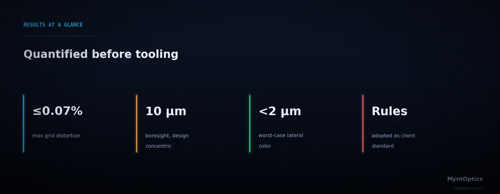
| Grid distortion (concentric mounting) | ≤0.07% maximum — negligible for the vision pipeline |
| Boresight shift over 15° camera rotation, pupil concentric | ~10 µm at the image plane (effectively calibration-stable) |
| Boresight shift over 15° rotation, pupil offset 10 mm | ~66 µm — quantified so the calibration strategy could account for it |
| Worst-case lateral chromatic aberration | Below 2 µm across the full 19° half field |
| Design rules delivered | Window radius > pupil-to-window separation; maximize radius short of TIR; minimize index — each backed by sensitivity curves |
The deliverable was not a single answer but a design-rule set with quantitative sensitivity curves, letting the client's mechanical team trade enclosure shape, window cost and optical performance with full visibility of the consequences.
Why This Matters
Enclosure windows, domes and covers are where good vision systems quietly go bad — they are usually specified by mechanical engineers with no optical feedback until units misbehave in the field. MyntOptics closes that loop early: we quantify what the "non-optical" parts of your product do to your optics, and we hand your team rules they can design against. The result here: an enclosure committed to tooling with known, bounded, calibrated optical consequences — no surprises after integration.
Putting cameras behind glass? Ask MyntOptics what that window will really do — while it is still cheap to change.
Have a similar engineering challenge? Talk to our optical engineers — a fixed-scope diagnostic turns uncertainty into a costed plan, typically within weeks.