Optical Transfer Function (OTF) Explained
Introduction: Why Optical Performance Is More Than Just Resolution
Why does the same scene appear sharp through one camera lens but noticeably softer through another, even when both lenses claim similar resolution specifications?
The answer lies in how accurately an optical system transfers detail, contrast, and structure from the object to the final image. To quantify this behavior, optical engineers rely on a comprehensive and system-level metric known as the Optical Transfer Function (OTF).
In practical terms, every optical system behaves like a spatial filter. Just as an audio filter affects low and high sound frequencies differently, an optical system affects coarse and fine image details referred to as spatial frequencies. The OTF describes exactly how this filtering occurs, making it one of the most important tools for evaluating real-world optical performance.
This article provides a practical, engineering-focused guide to evaluating optical image quality using the Optical Transfer Function (OTF) and Modulation Transfer Function (MTF). It explains what these metrics mean, how they are measured, and how to interpret OTF and MTF data when designing or evaluating real-world imaging systems.
If you are interested in how these metrics are applied during the development of real optical products, you may also find our overview of the custom optics design process useful.
Read the article here: https://myntoptics.com/the-journey-of-custom-optics-design
🎥 Video: Optical Transfer Function (OTF) and MTF Explained
For a visual, step-by-step explanation of Optical Transfer Function and Modulation Transfer Function concepts, watch the video below. It walks through how OTF and MTF relate to real-world image quality and how to interpret them in practice.
1. Fundamental Concepts: Resolution and Contrast
Understanding OTF begins with two foundational concepts in optical engineering: resolution and contrast.
Resolution in Optical Systems
Resolution refers to the ability of an imaging system to distinguish fine detail. It is commonly expressed in line pairs per millimeter (lp/mm), also known as spatial frequency. A line pair consists of one dark line and one adjacent bright line.
As spatial frequency increases, the optical system must resolve finer detail over the same physical distance. This places increasing demands on lens quality, sensor sampling, and system alignment.
Contrast and Image Fidelity
Contrast describes how effectively an optical system distinguishes light and dark regions in an image.
For a test target consisting of alternating black and white bars, contrast is defined as:
Contrast = (I_max − I_min) / (I_max + I_min)
In real optical systems, diffraction and aberrations blur sharp transitions. Dark regions become brighter, bright regions become dimmer, and overall contrast is reduced particularly at higher spatial frequencies. This contrast loss is the dominant factor that limits perceived image sharpness.
2. Optical Transfer Function (OTF): Definition and Meaning
The Optical Transfer Function (OTF) describes how an optical system transfers both contrast (amplitude) and phase (spatial position) from object to image as a function of spatial frequency.
Mathematically, the OTF is the normalized Fourier transform of the Point Spread Function (PSF) the image of an infinitesimally small point source. Because any image can be decomposed into spatial frequencies, the OTF provides a complete description of optical performance.
For sinusoidal object patterns:
- Image contrast is reduced
- Image features may shift spatially
The OTF captures both effects across the full range of spatial frequencies relevant to an imaging system.
3. Components of the Optical Transfer Function
The OTF is a complex-valued function with two distinct components, each describing a different aspect of image quality.
Modulation Transfer Function (MTF)
The Modulation Transfer Function (MTF) is the magnitude of the OTF and quantifies contrast transfer.
MTF(u) = Image Contrast(u) / Object Contrast(u)
An MTF value of 1 indicates perfect contrast reproduction, while an MTF of 0 indicates that no contrast is visible at that spatial frequency. Higher MTF values correspond to sharper, higher-quality image reproduction.
Phase Transfer Function (PhTF)
The Phase Transfer Function (PhTF) represents spatial shifts of image features relative to their ideal positions. Phase behavior is particularly important in precision imaging, metrology, and machine vision applications, where spatial accuracy is critical.
Large phase variations can indicate distortion or, in extreme cases, contrast inversion.
4. How OTF and MTF Are Measured in Practice
While sinusoidal test patterns are useful conceptually, practical MTF measurements typically rely on more efficient test targets combined with Fourier analysis.
Common industry measurement methods include:
- Point Spread Function (PSF): Imaging a point source (pinhole or microsphere) and computing the Fourier transform of the resulting blur spot.
- Line Spread Function (LSF): Imaging a narrow slit to generate high signal-to-noise MTF data in a single orientation.
- Slanted-Edge Method: Imaging a tilted sharp edge and extracting continuous MTF data across a wide spatial frequency range from a single capture.
These methods are widely used in lens testing, camera characterization, and imaging system validation.
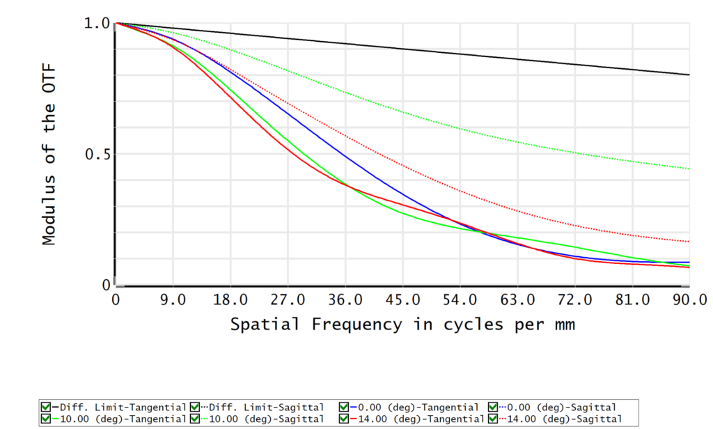
5. How to Read an MTF Chart
An MTF chart is the standard way optical designers communicate lens performance. Understanding its structure is essential for proper interpretation.
Key elements of an MTF chart include:
- Vertical axis: Contrast or modulation (0–100%)
- Horizontal axis: Spatial frequency (lp/mm)
- Diffraction limit: Theoretical maximum performance imposed by the wave nature of light
- Field positions: On-axis (center), mid-field, and full-field (corner) performance (several fields can be added)
- Sagittal and Tangential curves: Directional performance differences caused by off-axis aberrations
A high-performance optical system maintains high contrast and minimal separation between sagittal and tangential curves across the image field.
6. Why OTF and MTF Matter at the System Level
Imaging system performance is inherently multiplicative:
MTF_system = MTF_lens × MTF_sensor × MTF_other_components
Every component in the imaging chain degrades final image quality. A high-quality lens paired with a poor sensor will still result in a low-performance system.
This is why OTF and MTF are indispensable in optical system design. They allow engineers to predict system performance before hardware is built, identify performance bottlenecks, and balance cost against image quality requirements.
Conclusion: Using OTF to Design Better Imaging Systems
The Optical Transfer Function provides a complete and quantitative description of optical performance, linking theoretical design to real-world imaging behavior.
By understanding OTF, MTF, and their practical interpretation, engineers and system designers can make informed decisions that lead to sharper images, more reliable performance, and better-optimized optical systems.
MyntOptics is an optical engineering and design services company focused on translating fundamental optical theory into robust, system-level solutions. Through physics driven modeling, simulation, and performance analysis, we support imaging, machine vision, and advanced optical applications from concept through validation. Learn more about our optical design and system analysis capabilities at https://myntoptics.com/
#Optical Design #Optics Consulting #OpticalEngineeringServices